- 您现在的位置:买卖IC网 > Sheet目录333 > ISL6210CRZ (Intersil)IC MOSFET DRIVER DUAL SYNC 16QFN
�� �
�
�ISL6210�
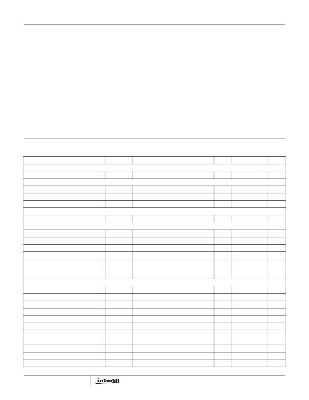
�Absolute� Maximum� Ratings�
�Thermal� Information�
�Supply� Voltage� (PVCC,� VCC)� .� .� .� .� .� .� .� .� .� .� .� .� .� .� .� .� .� .� .� .� -0.3V� to� 7V�
�Thermal� Resistance� (Notes� 1� and� 2)�
�θ� JA� (°C/W)�
�θ� JC� (°C/W)�
�Input� Voltage� (V� EN� ,� V� PWM� )� .� .� .� .� .� .� .� .� .� .� .� .� .� .� .� -0.3V� to� VCC� +� 0.3V�
�BOOT� Voltage� (V� BOOT-GND� ).� .� .� -0.3V� to� 33V� (DC)� or� 36V� (<200ns)�
�BOOT� To� PHASE� Voltage� (V� BOOT-PHASE� )� .� .� .� .� .� .� -0.3V� to� 7V� (DC)�
�-0.3V� to� 9V� (<10ns)�
�PHASE� Voltage� .� .� .� .� .� .� .� .� .� .� .� .� .� .� .� .� .� .� .� .� .� GND� -� 0.3V� to� 30V� (DC)�
�GND� -8V� (<20ns� Pulse� Width,� 10μJ)�
�UGATE� Voltage� .� .� .� .� .� .� .� .� .� .� .� .� .� .� .� .� V� PHASE� -� 0.3V� (DC)� to� V� BOOT�
�V� PHASE� -� 5V� (<20ns� Pulse� Width,� 10μJ)� to� V� BOOT�
�LGATE� Voltage� .� .� .� .� .� .� .� .� .� .� .� .� .� .� .� GND� -� 0.3V� (DC)� to� VCC� +� 0.3V�
�GND� -� 2.5V� (<20ns� Pulse� Width,� 5μJ)� to� VCC� +� 0.3V�
�Ambient� Temperature� Range� .� .� .� .� .� .� .� .� .� .� .� .� .� .� .� .� .� .-40°C� to� +125°C�
�QFN� Package� .� .� .� .� .� .� .� .� .� .� .� .� .� .� .� .� .� .� 46� 8.5�
�Maximum� Junction� Temperature� .� .� .� .� .� .� .� .� .� .� .� .� .� .� .� .� .� .� .� .� .� .� +150°C�
�Maximum� Storage� Temperature� Range� .� .� .� .� .� .� .� .� .� .-65°C� to� +150°C�
�Pb-Free� Reflow� Profile.� .� .� .� .� .� .� .� .� .� .� .� .� .� .� .� .� .� .� .� .� .� .� .� .see� link� below�
�http://www.intersil.com/pbfree/Pb-FreeReflow.asp�
�Recommended� Operating� Conditions�
�Ambient� Temperature� Range.� .� .� .� .� .� .� .� .� .� .� .� .� .� .� .� .� .-10°C� to� +100°C�
�Maximum� Operating� Junction� Temperature.� .� .� .� .� .� .� .� .� .� .� .� .� +125°C�
�Supply� Voltage,� VCC� .� .� .� .� .� .� .� .� .� .� .� .� .� .� .� .� .� .� .� .� .� .� .� .� .� .� .� .� .� 5V� ±� 10%�
�CAUTION:� Do� not� operate� at� or� near� the� maximum� ratings� listed� for� extended� periods� of� time.� Exposure� to� such� conditions� may� adversely� impact� product� reliability� and�
�result� in� failures� not� covered� by� warranty.�
�NOTES:�
�1.� θ� JA� is� measured� in� free� air� with� the� component� mounted� on� a� high� effective� thermal� conductivity� test� board� with� “direct� attach”� features.�
�2.� θ� JC� ,� “case� temperature”� location� is� at� the� center� of� the� package� underside� exposed� pad.� See� Tech� Brief� TB379� for� details.�
�Electrical� Specifications�
�These� specifications� apply� for� T� A� =� -10°C� to� +100°C,� Unless� Otherwise� Noted.� Parameters� with� MIN� and/or�
�MAX� limits� are� 100%� tested� at� +25°C,� unless� otherwise� specified.� Temperature� limits� established� by�
�characterization� and� are� not� production� tested.�
�PARAMETER�
�SYMBOL�
�TEST� CONDITIONS�
�MIN�
�TYP�
�MAX�
�UNITS�
�SUPPLY� CURRENT�
�Bias� Supply� Current�
�I� VCC�
�PWM� pin� floating,� V� VCC� =� 5V�
�-�
�170�
�-�
�μA�
�POWER-ON� RESET�
�POR� Rising�
�POR� Falling�
�Hysteresis�
�-�
�2.6�
�-�
�3.4�
�3.0�
�400�
�4.2�
�-�
�-�
�V�
�V�
�mV�
�BOOTSTRAP� DIODE�
�Forward� Voltage� Drop�
�V� F�
�V� VCC� =� 5V,� forward� bias� current� =� 2mA�
�0.3�
�0.60�
�0.7�
�V�
�PWM� INPUT�
�Sinking� Impedance�
�Source� Impedance�
�Three-State� Rising� Threshold�
�Three-State� Falling� Threshold�
�R� PWM_SNK�
�R� PWM_SRC�
�V� VCC� =� 5V�
�V� VCC� =� 5V�
�8.0�
�8.3�
�1.08�
�3.4�
�10.4�
�10.6�
�1.3�
�3.65�
�15�
�25�
�1.5�
�3.98�
�k� Ω�
�k� Ω�
�V�
�V�
�Three-State� Shutdown� Holdoff� Time�
�Three-state� to� UG/LG� Rising� Propagation�
�t� TSSHD�
�t� PTS�
�t� PDLU� or� t� PDLL� +� Gate� Falling� Time�
�-�
�-�
�80�
�20�
�-�
�-�
�ns�
�ns�
�Delay�
�SWITCHING� TIME� (See� Figure� 1)�
�UGATE� Rise� Time� (Note� 4)�
�LGATE� Rise� Time� (Note� 4)�
�UGATE� Fall� Time� (Note� 4)�
�LGATE� Fall� Time� (Note� 4)�
�UGATE� Turn-Off� Propagation� Delay�
�LGATE� Turn-Off� Propagation� Delay�
�UGATE� Turn-On� Propagation� Delay�
�LGATE� Turn-On� Propagation� Delay�
�UGATE� Turn-On� Propagation� Delay�
�LGATE� Turn-On� Propagation� Delay�
�Minimum� LGATE� On� Time� in� DCM� (Note� 4)�
�t� RU�
�t� RL�
�t� FU�
�t� FL�
�t� PDLU�
�t� PDLL�
�t� PDHU�
�t� PDHL�
�t� PDHU�
�t� PDHL�
�t� LGMIN�
�V� VCC� =� 5V,� 3nF� Load�
�V� VCC� =� 5V,� 3nF� Load�
�V� VCC� =� 5V,� 3nF� Load�
�V� VCC� =� 5V,� 3nF� Load�
�V� VCC� =� 5V,� Outputs� Unloaded�
�V� VCC� =� 5V,� Outputs� Unloaded�
�V� VCC� =� 5V,� Outputs� Unloaded;� R� SET� =� 0� Ω�
�V� VCC� =� 5V,� Outputs� Unloaded;� R� SET� =� 0� Ω�
�V� VCC� =� 5V,� Outputs� Unloaded;� R� SET� =� 80k� Ω�
�V� VCC� =� 5V,� Outputs� Unloaded;� R� SET� =� 80k� Ω�
�-�
�-�
�-�
�-�
�-�
�-�
�-�
�-�
�-�
�-�
�-�
�8.0�
�8.0�
�8.0�
�4.0�
�20�
�27�
�26�
�26�
�41�
�33�
�400�
�-�
�-�
�-�
�-�
�-�
�-�
�-�
�-�
�-�
�-�
�-�
�ns�
�ns�
�ns�
�ns�
�ns�
�ns�
�ns�
�ns�
�ns�
�ns�
�ns�
�4�
�FN6392.1�
�December� 9,� 2008�
�发布紧急采购,3分钟左右您将得到回复。
相关PDF资料
ISL6244EVAL1
EVALUATION BOARD ISL6244
ISL6261AEVAL1Z
EVAL BOARD 1 FOR ISL6261A
ISL6261EVAL1Z
EVAL BOARD FOR ISL6261 1 QFN
ISL6271AEVAL1
EVALUATION BOARD FOR ISL6271A
ISL62882CEVAL2Z
EVAL BOARD FOR ISL62882C
ISL62883CEVAL2Z
EVAL BOARD FOR ISL62883C
ISL62883EVAL2Z
EVALUATION BOARD FOR ISL62883
ISL62884CEVAL2Z
EVAL BOARD FOR ISL62884C
相关代理商/技术参数
ISL6210CRZ-T
功能描述:IC MOSFET DRIVER DUAL SYNC 16QFN RoHS:是 类别:集成电路 (IC) >> PMIC - MOSFET,电桥驱动器 - 外部开关 系列:- 标准包装:50 系列:- 配置:高端 输入类型:非反相 延迟时间:200ns 电流 - 峰:250mA 配置数:1 输出数:1 高端电压 - 最大(自引导启动):600V 电源电压:12 V ~ 20 V 工作温度:-40°C ~ 125°C 安装类型:通孔 封装/外壳:8-DIP(0.300",7.62mm) 供应商设备封装:8-DIP 包装:管件 其它名称:*IR2127
ISL6211
制造商:INTERSIL 制造商全称:Intersil Corporation 功能描述:Crusoe⑩ Processor Core-Voltage Regulator
ISL6211CA
制造商:Rochester Electronics LLC 功能描述:CPU REGULATOR FOR TRANSMETA,SINGLE CORE - Bulk 制造商:Intersil Corporation 功能描述:
ISL6211CA WAF
制造商:Intersil Corporation 功能描述:
ISL6211CA-T
制造商:Rochester Electronics LLC 功能描述:CPU REGULATOR FOR TRANSMETA,SINGLE CORE - Tape and Reel 制造商:Intersil Corporation 功能描述:
ISL6215CA
制造商:Rochester Electronics LLC 功能描述:C4AM,PRECISION MULTI-PHASE BUCK PWM CONT - Bulk
ISL6215CA-T
功能描述:电压模式 PWM 控制器 C4AM,PRECISION MULTI-PHASE BUCK PWM CONT RoHS:否 制造商:Texas Instruments 输出端数量:1 拓扑结构:Buck 输出电压:34 V 输出电流: 开关频率: 工作电源电压:4.5 V to 5.5 V 电源电流:600 uA 最大工作温度:+ 125 C 最小工作温度:- 40 C 封装 / 箱体:WSON-8 封装:Reel
ISL6216/17MB-EV1
制造商:Intersil Corporation 功能描述:ISL6216/17MB EVALUATION BOARD - Bulk